Power supply failure is one of the most common problems faced by PC users. If your power supply fails then your PC won’t turn on and it can hamper your work. A faulty power supply is not easy to detect because it cannot be monitored through any software and the fault can be diagnosed by testing only. It can get further difficult to detect the fault when the power supply is turning on but one of the voltage rails is not functioning properly and giving out improper voltages, which is quite dangerous and can cause damage to your internal components. Whenever your PC does not start, the first component to check is the power supply but most of the users don’t know how to test a power supply and diagnose it for fault and errors. So, to help you out on this matter, here I will tell you how to test a power supply for any errors or failures to make sure that your PSU is working properly or not.
How to Test Power Supply of PC
Here are the various methods by which you can check or test the Power Supply Unit (PSU) of the PC.
Basic Power ON Test (Jumper Method)
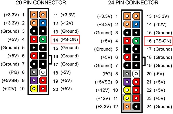
It is a basic Power ON test to check whether the PSU is starting or not. It is done by shortening the Power Supply ON (PS_ON) Signal Pin of the 24-pin or 20-pin ATX connector of the PSU with any one of the ground pins in the connector. For the 24-pin connector, it is PIN 16 and for the 20-pin connector, it is PIN 14. In the images below, you can see the green-colored Pins in the 24-pin and 20-pin connectors are ‘Power Supply On’ sensor pins.
Steps for Testing PSU without Motherboard
1. Unplug the PSU from the computer and mains.
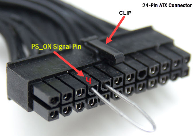
2. Hold the 24-pin or 20-pin connector in such a way that the connector clip is facing up and the pins toward you.
3. Now count the fourth and fifth pin from the top-left of the connector. Here the fourth pin is the ‘Power On’ sensor pin and the fifth pin is the ground pin.
4. Insert a paper clip, solid copper wire, or small wire in the 4th and the 5th pin you have located.
5. Plug the PSU cable into the mains power socket, turn ON the mains power, and also the power supply if the PSU has an ON/OFF switch.
6. If the PSU fan starts spinning then it means the PSU has started and is powered On.
Note: Some power supplies have a zero-RPM feature that results in the fan only spinning for a moment after the PSU is powered on. This still indicates that the PSU is functioning normally. However, in the case of passive PSUs without a fan, you have to attach a case fan to the 4-pin Molex connector of the PSU to check that the PSU has started.
Power Supply Jumper Bridge Tool
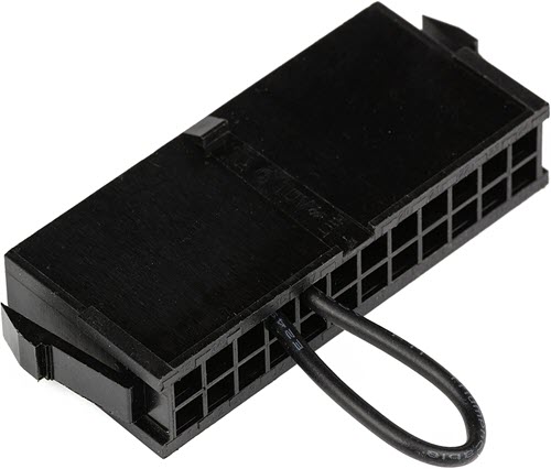
If you are not comfortable doing this jumper procedure manually then you can get a Power Supply Jumper Bridge Tool which can be plugged into the 24-pin/20-pin connector of the PSU to get the same result. Below is such a power supply jumper adapter and it supports both 20-pin and 24-pin connectors.
By Power Supply Jumper Bridge Tool
Testing Power Supply Rails & Connectors
The jumper method can only tell you that the PSU is powering up but it does not tell you whether all the voltage rails are functioning properly and the connectors are outputting proper voltages. So, to test the voltage rails and connectors, you have to use the below-mentioned methods.
Using Multimeter
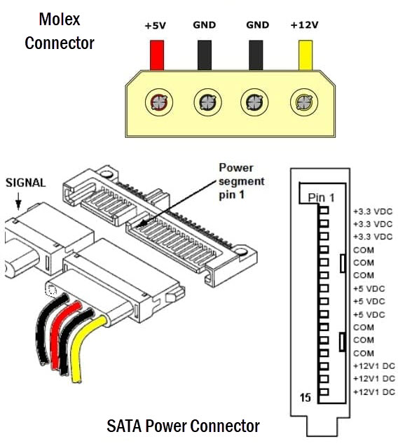
You can use a basic and inexpensive multimeter to check the PSU rails by measuring the voltages across various connectors of the power supply. It is also used to check the connectors of the PSU and whether they are outputting proper voltages. If the voltage levels are significantly lower or higher than the reference then it may cause damage to the components connected to the PSU. If you don’t have a digital multimeter then you can purchase it online. To test the various connectors and voltage rails, you have to know the connector pinout diagram and wire color coding for different voltages to get the reading on the multimeter. In almost all power supplies, the black wire is the common or ground wire, yellow is for +12V and the red one is for +5V. The orange color is used for +3.3V.
How to Test Voltage Rails & Connectors using Multimeter
1. Unplug the PSU connectors and make sure the power supply is not connected to the mains.
2. Start the PSU by shortening the “Power On” pin with the ground pin by following the jumper method mentioned above in this post.
3. Set your digital multimeter on DC mode.
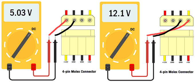
4. Now, suppose you want to check the 4-pin Molex connector that outputs both +12V and +5V. First, connect the Red lead of the multimeter to the Red wire pin of the Molex connector and the Black wire to any ground wire of the Molex connector. If the +5V voltage rail is working properly then your multimeter will show voltage close to 5V. Similarly, to test +12V, connect the Red lead of the multimeter to the Yellow wire pin and Black lead to any black wire pin of the Molex connector. If it is working fine then your multimeter will show a voltage at around 12V with a slight variation.
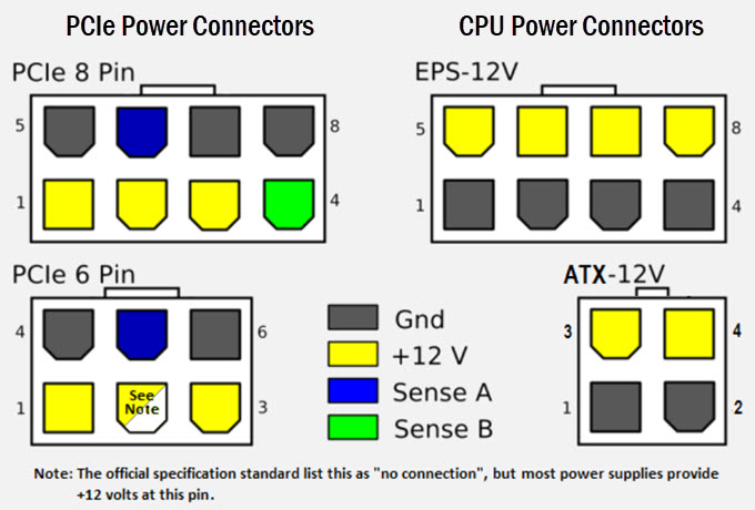
5. Using the same principle or procedure, you can check other PSU connectors by following the Pinout diagrams of the connectors. Below are the Pinout diagrams of various connectors of the PSU.
The voltage reading should not deviate too much from the reference or specified voltage output of the rail e.g. the voltage reading of a 12V Rail should not be showing 10V or 14V. The same thing is applicable for other rails that include 5V and 3.3V. The Intel Standard for different Voltage Rails are shown below:
| Voltage | Intel Standard | |
| Minimum | Maximum | |
| +5V | 4.75V | 5.25V |
| +3.3V | 3.1V | 3.5V |
| +12V | 11.4V | 12.6V |
| -12V | -10.8V | -13.2V |
| +5Vsb | 4.75V | 5.25V |
Note: You still have to short the PSU ‘Power On’ pin with the ground pin using the jumper method to start the PSU for testing the voltage levels on the various connectors.
Must Remember for a PC Power Supply Connector
Black wire – Ground or Negative
Yellow –> +12V
Red –> +5V
Pink or Orange –> +3.3V
Power Supply Tester
A Power Supply Tester is a small device that is used to check and diagnose a PSU. It can give out the voltage reading of all Rails (+12V/+5V/+3.3V/5VSB/ 12V) and can also tell you whether there is something wrong with the power supply or it is functioning properly. Generally, a power supply tester has a small LCD screen attached to it that shows you the voltage output on all the Rails. It also displays PG or “Power Good” parameter that is used to detect any abnormality with the PSU. Generally, Power good values are often considered abnormal if detected lower than 100ms or higher than 500ms for the most power supply testers available in the market today.
How to use a Power Supply Tester
- Turn Off the PSU.
- Connect the 20-pin/24-pin connector and other connectors (Molex/SATA/PCIe/EPS) to the PSU Tester.
- Turn On the PSU and the Power Supply Tester (if it has an On/Off button)
- The voltage readings for different voltage rails and PG (Power Good) values will be shown on the LCD screen of the power supply tester device. In case of any abnormality, a beep or other alarm sound will trigger.
Best Power Supply Tester Devices
Here are some of the best Power Supply Testers you can buy to check and test the PSUs.
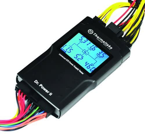
Thermaltake Dr.Power II
If you are looking for a power supply tester from a well-known and reputable brand then Thermaltake Dr.Power II is what you should buy. It is also of the best power supply testers available in the market. The PSU tester comes with a larger LCD that is easy to read and shows you all the relevant information about the various important parameters of the PSU. It supports all the ATX power supplies up to ATX12V v2.3. The power supply tester is very easy to use and you just have to plug in the connectors (24-pin, Molex, PCIe, EPS, SATA), press the power button on the side, and then it displays the voltages for +12V/+5V/+3.3V/5VSB/-12V Rails. The PG or ‘Power Good’ value should between 100 ms to 500 ms. If you are getting a 0 ms value, then it means the power supply is dead and not functioning. The device has built-in output connectors diagnostic system, low-voltage, high-voltage, no voltage, PG alarm systems to notify you of any errors, instability, or abnormal behavior with the power supply.
Buy Thermaltake Dr.Power II Power Supply Tester
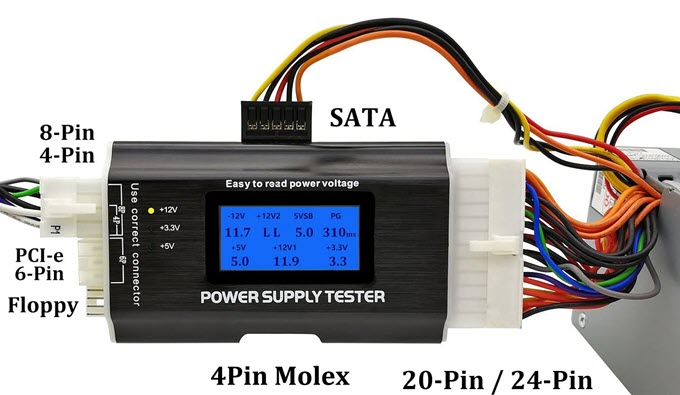
Generic PC Power Supply Tester
A generic power supply tester with a metal body made of aluminum alloy. It comes with a 1.8” LCD Screen that shows the voltages of various rails and PG value. To use the device, just insert the 20-pin or 24-pin and P4, P6, or P8 plug into the corresponding position of the power tester. If the 4P connector is not inserted then the power supply tester displays “LL”. If the values of each group do not flash, it indicates that the power input of this power supply is normal. If the voltage signal of a circuit is not detected (such as a 20-pin or 24-pin connector) or the detected voltage exceeds the normal range, the buzzer will send out a warning sound for a long time. If the corresponding voltage or PG value display status is flashing, it means that the power supply is at fault. The voltage of the SATA / P6 / P8 interface is displayed by the three lights on the left of the power tester. If their voltage is normal, the three groups of lights (+ 12V, + 3.3, + 5V) will be ON. If the light is not ON, it indicates that the interface line group is faulty.
Buy Generic PC Power Supply Tester
PSU Stress Test Software
If you want to stress-test your power supply for any weakness then you can do so by using OCCT software, which is one of the best all-in-one stability check & stress test tools available. You can download its free version from the link given below.
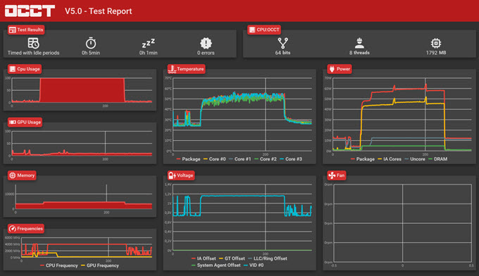
Note: OCCT stress test tool puts a lot of stress on your components and if you are not sure how to use it then it may cause damage to your components and may fry them if they could not handle the stress over the running period of the test.
Download OCCT Stress Test Tool
See also:
- What Power Supply do you need? [PSU Buying Guide]
- Fix ‘PSU Fan not Spinning] Problem
- Power Supply Overheating Symptoms & Solutions
- How to Find out your Power Supply Specifications?
- Best PC Power Supply Calculator Tools
Queries?
If you have queries regarding the power supply testing or troubleshooting then you can ask them in the comment section below.
(*This post may contain affiliate links, which means I may receive a small commission if you choose to purchase through the links I provide (at no extra cost to you). Thank you for supporting the work I put into this site!)
![Fix ‘PC Won’t Turn ON’ [Top Causes & Solutions]](https://graphicscardhub.com/wp-content/uploads/2021/09/PC-wont-turn-on-211x150.jpg "Fix ‘PC Won’t Turn ON’ [Top Causes & Solutions]")

![Calculate SSD Lifespan in Years [Know How Long it will Last]](https://graphicscardhub.com/wp-content/uploads/2019/08/ssd-lifespan-calculate-211x150.jpg "Calculate SSD Lifespan in Years [Know How Long it will Last]")
Very good sir I agree with everything you said I’m a I can say a little more than a hobbyist I make my own circuits and stuff now I’m learning and I’ve learned the hard way and I figured it all out and everything you said right on time really cool thank you I just thought I’d read it , greg
Yes I failed to mention on yes you did too that don’t venture too far into them power units because they can be dangerous and they can really suck the car out of you or kill you so follow the directions don’t go any further than what he said and you should be all right or I would just take it to a professional if you don’t know anything about it thank you for your time,
Greg
You failed to mention anything about testing under a load condition. Most PS will test ok with a multi-meter, but when you put a load on them will show a weak PS.
WEll, you can use OCCT stress test tool for stress testing to get an idea about the stability of the PSU.
SO, let me give you an example of what I am troubleshooting at the moment. I have an ASUS Z690 motherboard, a 1000 watt PS and a 2080Ti graphics card in my system. I am blowing video cards. When I put the card under stress (high 3D graphics) my system shuts down and reboots. I run OCCT and all is fine except video card which again shuts down and reboots system. This is the second video card to do this. Every test passes except 3d graphics. System is stable and running fine until playing a game or running graphics stress test. Your thoughts?
What PSU (brand & model) do you have? Also, what is GPU and VRAM temperature during load?
PSU is a EVGA https://www.newegg.com/evga-supernova-1000-g5-220-g5-1000-x1-1000w/p/N82E16817438160?Item=N82E16817438160&utm_medium=TraEmail&utm_source=TEMC-Shipping-New-Delivery-Notification-Responsive-USA&cm_mmc=TEMC-Shipping-New-Delivery-Notification-Responsive-USA-_-N82E16817438160
GPU is an Asus 2080Ti Temp between 54 and 65C
GPU temperature is fine. I think it could be an issue with the PSU and the only way to check this is to test your system with another PSU.
Power supply is less than a year old, but could be the problem. I was leaning more towards the motherboard because my disk active light stays on. In fact when I power down they are still on. I am wondering about USB hubs and their power. Does that power feed back through the USB connector to the PC? When I power down, I still have about 3.85 volts sitting on the 5V side.
“Does that power feed back through the USB connector to the PC?” (I don’t think so)
Well, a faulty motherboard could be a possibility if strange things are happening.
Where? (3.85 volts sitting on the 5V side)
What do you mean where? Everywhere the 5v goes.
3.85 volts at 5V Rail is quite low.
That’s coming from the hub back to my computer. It is actually quite high, it should be zero. I have been reading about the phenomena and it is quite common and can be quite bad especially in my configuration using a PC power supply for powering the hubs. The 850 watt power supply is substantial enough to harm the motherboard when something goes wrong. What i am wondering now is what power comes from the MB to the PCI slot the graphics card plugs into. Have to research that now.